 Michail Lyamaev
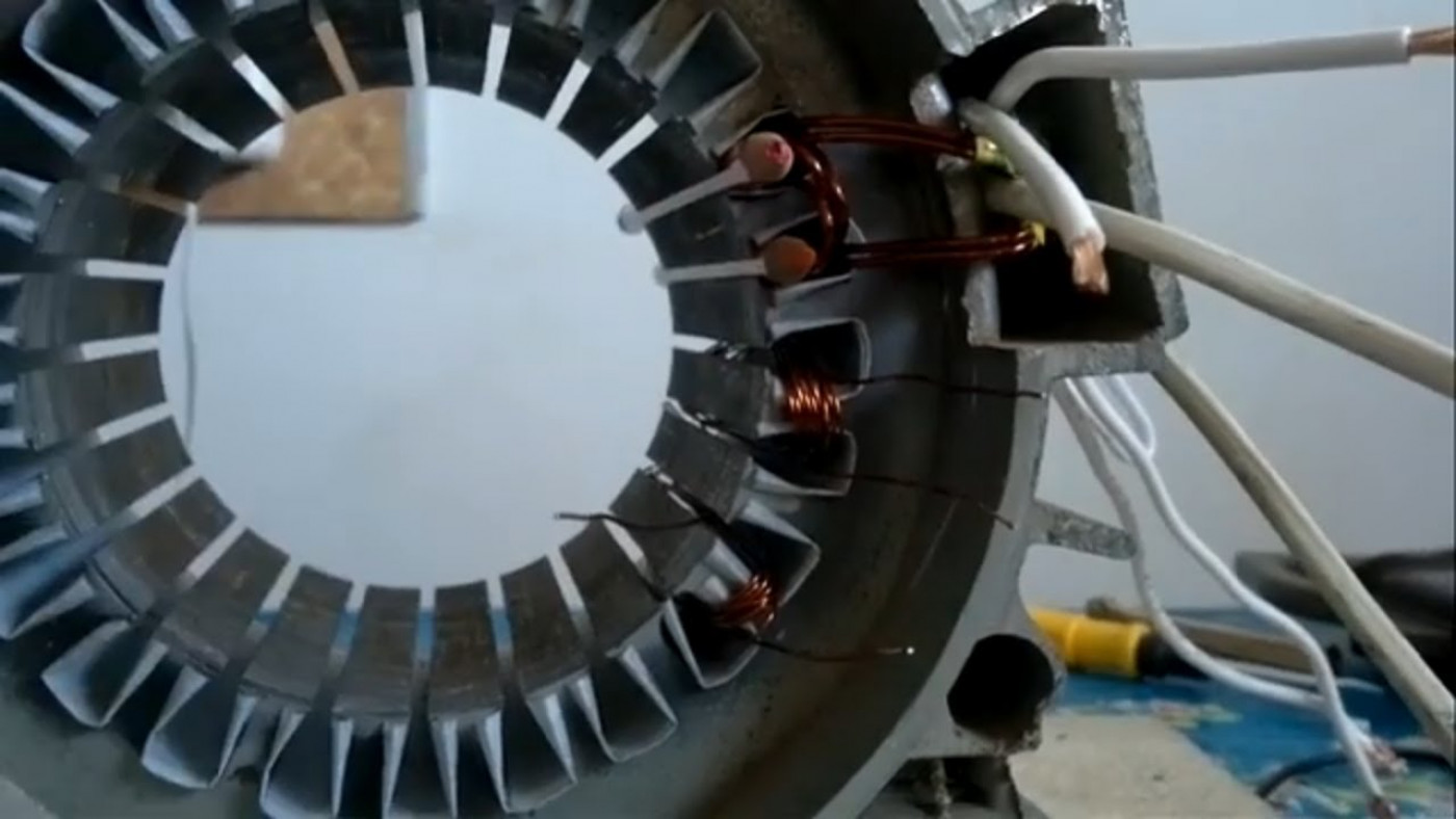
After the previously done work on the manufacture of our wind turbine, we have come to such a stage when it is necessary to measure the voltage of the test coil coil.
A bit of theory:
In order to correctly wind the windings and then correctly "make friends" EMF with the screw revolutions, we must already at this stage calculate the winding so that the screw and generator powers are consistent.
For example, suppose a wind turbine power is 300 watts at a wind speed of 10 m/s. A screw with a diameter of 2 meters is quite suitable for this. The two-meter screw has certain revolutions with a wind of 10-12 m/s. Also, this screw has certain revolutions in the wind of 4 m/s. We need to calculate the winding of the generator so that at 100 rpm (wind about 4 m/s), a voltage of 12 V is generated, and charging of the battery begins. And as the speed of the screw increased, the current increased, that is, the proportion of power removed from the screw was slightly more than the power removed from the generator. But not in excess of the big one, so that the screw does not go to outrageous revolutions and at the same time is not much less than the generator in power. Since in this case, the screw will not have enough power reserve to gain momentum.
Accordingly, now we need to find out what voltage the existing magnetic system will give in order to calculate the number of turns. Further, knowing the number of turns in each coil, we find out the number of turns in each phase, in three phases and the open circuit voltage of one phase. Then it is not difficult to calculate the open circuit voltage of 3 phases. As a result, at certain speeds, we already know the indicators of open circuit voltage. A section of the conductor is selected from the calculation of the groove area, the number of turns and the area of one conductor.
After the end of the project, all the calculated data will be in a separate table, and you can take the winding data, and make a generator on their basis.
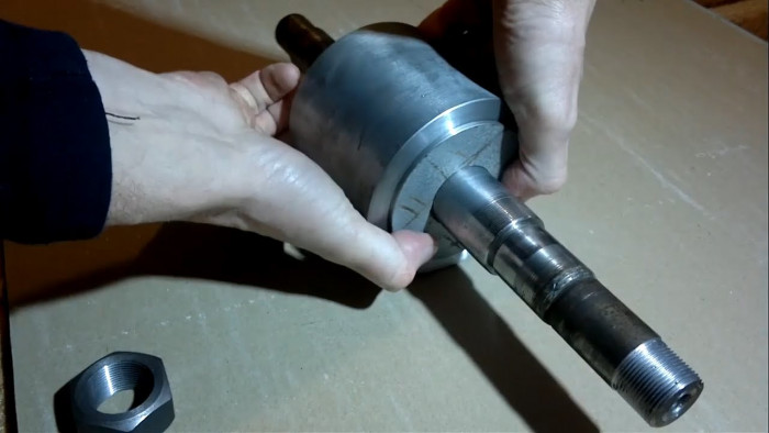
A little bit about the preparatory phase:
A thick conductor, 1 turn, was taken for the test. The next coil (in the picture) in the test coil for voltage recovery at certain revolutions contains 10 turns. And 3 coils for measuring frequency, it also has 10 turns to determine the number of revolutions per minute. It is important to know whether the voltage corresponds to the number of revolutions of the rotor. For example, 100 revolutions, a voltage of 2 Volts with 10 turns, and then the calculation is made on an increasing basis.
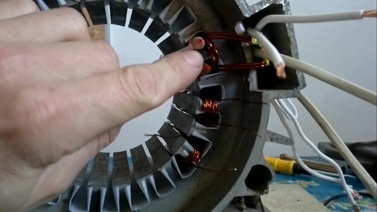
Sensors:
Coil for measuring frequency.
Coil for measuring the characteristics of one turn of the open circuit voltage.
Coil for measuring characteristics of open circuit voltage containing 10 turns.
Let's start:
For a small experiment, we measure the short-circuit current on a thick conductor and on a thin conductor at the same speed.
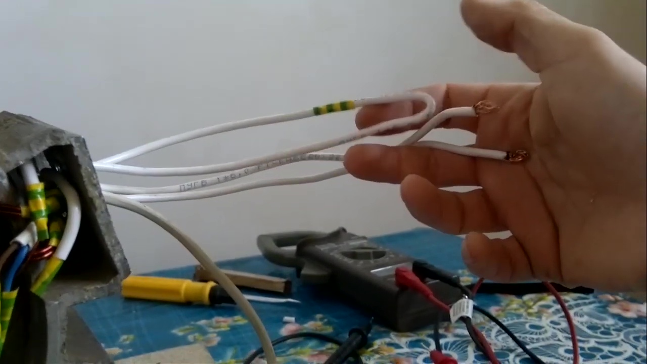
For the purity of the experiment, the length of the lead-out conductor is made of the same section and approximately the same length.
Let us measure the short-circuit current on thin windings with a cross section of 0.85 mm² at 50 Hz, which equals 230 revolutions of the shaft. At 50 Hz, the device showed about 7-8 A short circuit current on a thin conductor.
Next, we test the short circuit current of the coil with a thick conductor (cross section 4 mm²) at the same 50 Hz. At 50 Hz, the short-circuit current was 45 A.
The short circuit current depends on many parameters, but the short-circuit current cannot be used to judge the generator, especially if it is not a ready-made generator, but only testing.
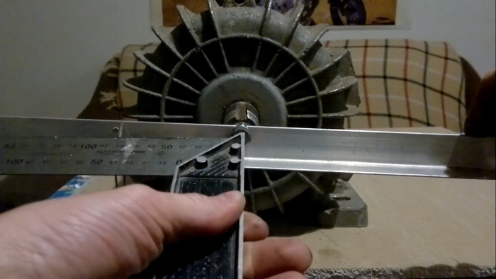
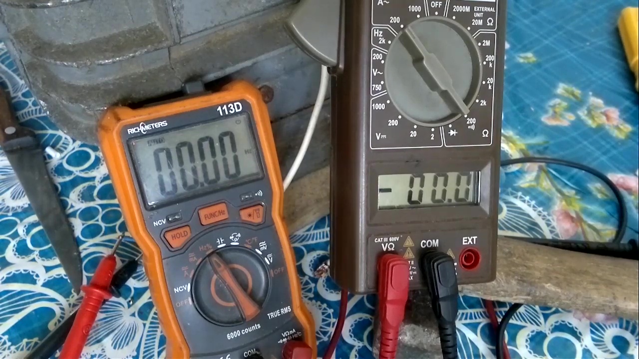
We proceed to determine the voltage of one turn for a given magnetic system. We will measure the open circuit voltage of an alternating current with a frequency of 50 Hz. During the experiment, we carefully monitor that the frequency is as close as possible to 50 Hz.
50 Hz because in 13 pairs of poles (namely, our magnetic system contains so much) we get 230 rpm, so we will know that at 230 rpm 10 test turns have a certain voltage. Our device is designed for industrial frequency and has no frequency adjustments, so if the frequency is above or below 50 Hz, the error increases.
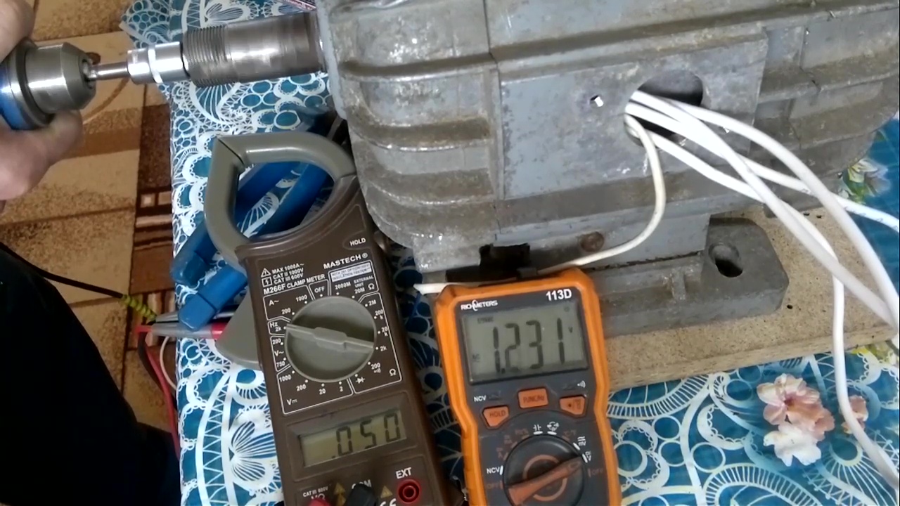
We are trying to spin up to 230 revolutions at 50 Hz with a drill, or at least try to get closer to the revolutions we need.
Measurements were taken at 3 frequencies of 46, 50 and 55 Hz.
Result:
46 Hz = 212 rpm = 1 V/10 turns = 0.1 volts per turn.
50 Hz = 230 rpm = 1.1 V/10 turns = 0.11 volts per turn.
55 Hz = 254 rpm = 1.27 V/10 turns = 0.127 volts per turn.