 Michail Lyamaev
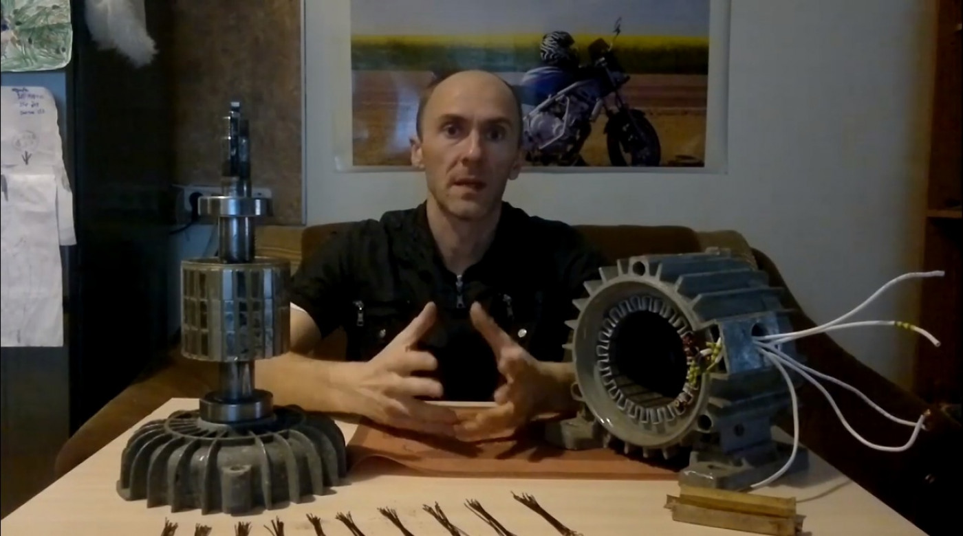
In today's article we will talk about the winding parameters, the number of turns, the cross section of the wire, the estimated energy, as well as the estimated number of revolutions.
We believe that the wind turbine will run on a system with a voltage of 24 V and a power of approximately 1 kW at a wind speed of 10-12 meters per second. The calculation of turns was performed by Alexey Tarasov, after in 6 articles the data of the test coil from 10 turns were received.
Why is it desirable to use exactly 24 volt system? At this power, the use of higher voltages is more appropriate for the safety of the windings. But in order for this windmill to be used in areas with a lower average wind speed (5-6 meters per second) it can be made universal. It will be suitable both for the 12-volt system, at rectification of each phase and in parallel, and for the 24-volt system at connection - "Star".
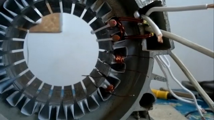
Operating speed of a wind turbine with a capacity of 1 kW, as practice shows, starts from 120 revolutions per minute. After calculations at 120 rpm, the voltage obtained was 26 volts, taking into account all losses, and the number of turns of one coil - 25. It is much easier to wind two coils of 25 turns than to wind everything in one coil, thus in one groove there will be two coils.
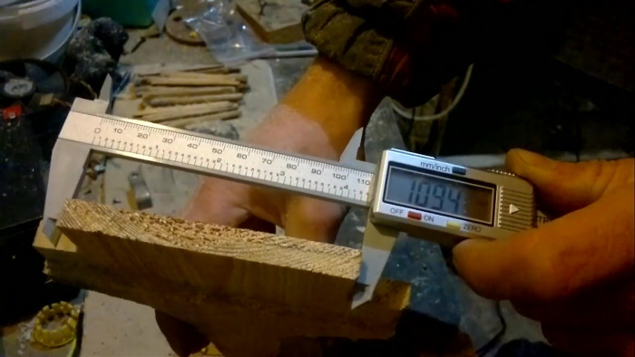
Next, you need to determine the conductor of which thickness will fit well in the groove so that the total number of turns reaches 50, ie 25 turns per coil and 25 per second.
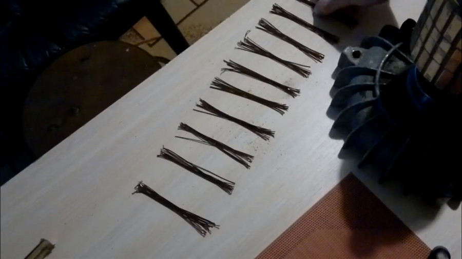
It was taken a wire with a thickness of 0.85 mm (0.9 mm with insulation), it must be wound in 2 cores of 25 turns, a total of 50 conductors, and they will occupy just half of the groove. For a wire with a thickness of 0.9 mm, its cross section - 0.64 mm square is multiplied by 2 conductors in one turn and we get 1.28 mm square - a cross section of one turn of the coil. Also, instead of two conductors 0.9 mm thick, you can take one conductor 1.3 mm thick, but it is less convenient to work with.
We will remind that at two thin conductors the filling factor outside is better than at one thick.
That's all for today, it is better not to start the action, but wait for the article in which we will wind the coils to find out whether we succeeded or not.